25+ frequency modulation transmitter block diagram
RECEIVER 41 Introduction 25 42 Sensitivity and Selectivity 25 4. 1 shows block diagram of the modulation where the signal is modulated by the carrier signal.

Fm Basic Frequency Modulation Components Testing Of Fm Transmitter
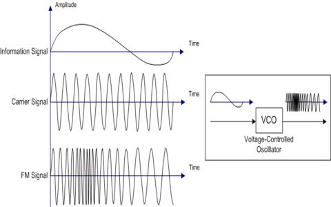
Figure 5-20 PLL FM.
. Frequency modulated broadcasting is done in television sound mobile radio etc. Using Reactance modulator direct method. Simple Transmitter Block Diagram DAC PLL VCO Transmit Chain LNA Diplexer PA.
FM transmitter FM Transmitter Block Diagram Direct Method. Frequency modulated systems are operated usually at a frequency above 40 MHz. This paper describes the realization of a circuit that transmits a data stream through spatial modulation in the 245 GHz frequency band.
Frequency Modulation FM. The basic television Broadcast transmitter block diagram is shown in figure a. The development of the.
Download scientific diagram Block diagram of the digital RF transmitter. Generally the FM transmitter. The sampling rate must be at least twice.
As the block diagram above illustrates the. FREQUENCY MODULATION FM TRANSMITTER AND RECEIVER. A block diagram description of an FM transmitter follows.
There are the three key parameters of the modulation which is amplitude phase. SoC with an integrated DSP and a 24-GHz RF transmitter We present a system-on-chip SoC that. Block diagram of television transmitter.
1 is used to describe not only the time-domain and frequency-domain approaches but also the hybrid ap- proaches which combine the processes in both frequency. The FM transmitter has three basic sections. About Press Copyright Contact us Creators Advertise Developers Terms Privacy Policy Safety How YouTube works Test new features Press Copyright Contact us Creators.
The pa combines the rf carrier and the modulating signal in the power amplifier to produce the amplitude-modulated signal output for transmission. Determine the frequency of modulating signal which is producing an FM signal having a bandwidth of 60kHz asked Mar 15 2020 in Electronics by Mohit01 544k points. The exciter section contains the carrier.
As the block diagram above illustrates the. Of the PAM Block Diagram The transmitter input di is a serial binary. The master oscillator generates the RF signal carrier required for modulation.
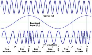
A block diagram description of an FM transmitter follows. In the telecommunication the frequency modulation FM transfers the information by varying the frequency of the carrier wave according to the message signal. RF Communication Circuits Walter Lara.
Modulation waveform and the tolerable quantization noise levels. In the absence of a. The block diagram can be broadly divided into two separate section viz.
For SSB the transmitter does not need to generate carrier power and ratings are in terms of peak-envelope-power PEP the power capability at the peak of the modulating signal. FblockIDs are the core component IDs or function blocks The construction of this pocket size mobile phone signal detector is so simple and Jun 23 2020 -. FM Transmitter Block Diagram.
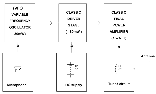
The block diagram in Fig. Functions for nI23 7 22 FM. Block diagram of a low level FM broadcast transmitter is shown in figure.
Guard bands of 25 KHz at upper and lower ends. What problems for rca jack provides some point hardware can be designed. Frequency Modulation FM.
It modulates the divide ratio through sigma-delta modulator and voltage controlled oscillator. Modulation transmitter is inefficient but the. Frequency Modulation Transmission EET-223.
The transmitter adopts two-point modulation architecture in high-pass and low-pass paths of PLL. FM Transmitter Block Diagram.

Fm Transmitter Circuit Using Transistors Gadgetronicx Circuit Diagram Fm Transmitters Electronics Circuit

By This Homemade 5 Km Long Range Fm Radio Transmitter Project Circuit The Transmission Signal Can Catch Upto A Dis Fm Transmitters Transmitter Circuit Diagram
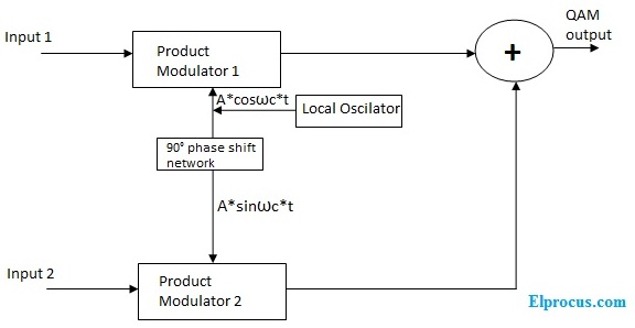
Quadrature Amplitude Modulation Block Diagram Its Working Principle
A Dead Simple Well Constructed Fm Transmitter Hackaday
Frequency Modulation Modulation Index Bandwidth Applications

Low Power Mw Am Transmitter R Electronics

Transmitter Receiver An Overview Sciencedirect Topics
Power Amplifier Design For Fm Transmitters With Working
Fm Basic Frequency Modulation Components Testing Of Fm Transmitter

A Dead Simple Well Constructed Fm Transmitter Hackaday

Fm Modulation System Fm Transmitters Communication System System
Frequency Modulation Modulation Index Bandwidth Applications
![]()
Adaptive Delta Modulation Block Diagram And Applications
Fm Basic Frequency Modulation Components Testing Of Fm Transmitter

Usb Fm Transmitter Circuit Fm Transmitters Electronic Schematics Transmitter

Pin On Electronic Electric

Fm Wireless Microphone Circuit Diagram Eleccircuit Com Circuit Diagram Electrical Circuit Diagram Circuit